What We Are Doing
We are going to turn a PC power in to a fixed voltage power supply for desktop use for powering any of your projects that need 12V 5V or 3.3V or simply for powering up computer devices without them being in the system EG fans water pumps ect. I choosed a small form factor PSU for the reason I didn't really want to have a big case on my desk the steps below will apply to any size PC power supply.
Parts Needed
1x Pc Power Supply
2x Green Led
2x Led Holder
2x 1.5K Resistors
3x Fuse Inline Fuse Holder
3x 3 Amp Fuse
6x Eye Crimp Terminals
1x Toggle Switch
1x Blank Molex Plug
1x Case to fit Power Supply
1x Spindle of Wire Black
1x Spindle of Wire Red
1x Spindle of Wire Green
(1x Spindle of Wire Yellow if avalible)
1x Yellow Banana Plug Socket
1x Red Banana Plug Socket
1x Green Banana Plug Socket
3x Black Banana Plug Socket
1x Green Banana Plug
2x Yellow Banana Plug
6x Black Banana Plug
6x Red Banana Plug
2x Alligator clips Red
2x Alligator clips Black
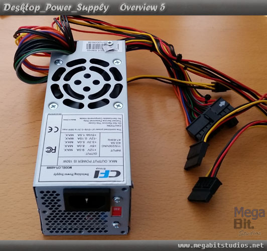
Power Supply / Case
I pick this power supply so it would fit in to a small case thus not taking up a lot of desk space.
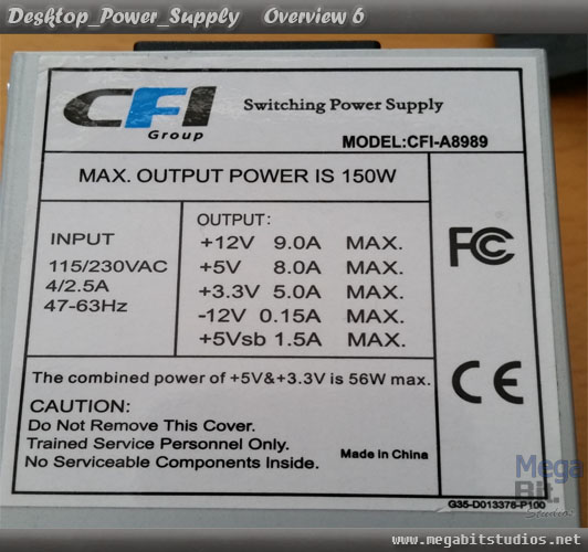
Fuse
The reason for only a 3A fuse is because i do not need a lot of current draw and i am happy with it being limited to 3A by the fuse, if you wish you can put as big of a fuse as you like just make sure you don't select one that is bigger than the max current you can draw from the power supply eg you may only have a 12V rail that can handle 11 Amps so to be safe put a 10A fuse.
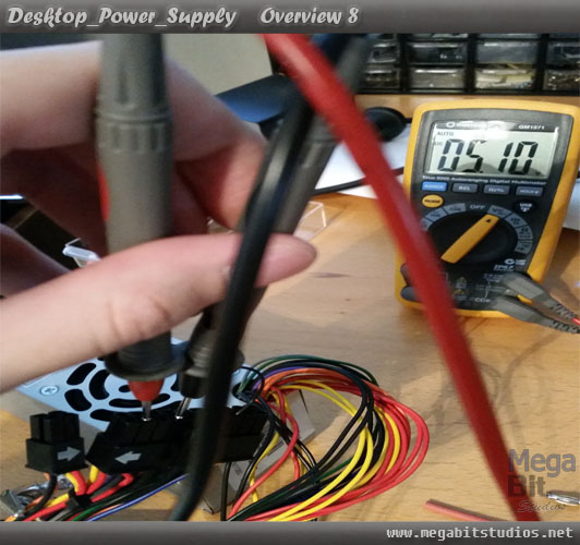
Test The PSU
Ok in this step we are going to test the power supply to see if it is work, and is out putting the correct voltages, doing this now will save you a head ache in the future if the power supply does not work.
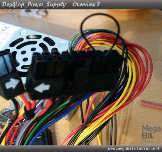
what you want to do is get a small bit of wire or a paper click and short out the Green Wire from the 24Pin Connector to a black wire this will tell the power supply to start. once you have done that plug the PSU in to the wall and turn it on be careful not to let the wire or paper clip touch the body of the PSU.
Now grab your maltymeter and test the voltages put the black lead on to one of the black wires then put the red lead on to the orange wire which will give you a 3.3V, then the red wire witch then should read 5V and lastly the yellow wire witch should read 12V.
If all of the voltage read in between +0.2V and -0.2V and are stable then your good to go your PSU is working normally if your voltage is out by more that this and is not stable then throw the PSU put and grab another one.
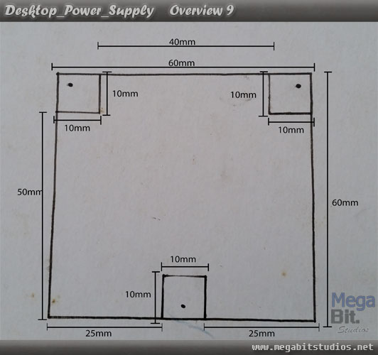
Template & Cutting
Now we need to work out how to fit the power supply in to the case and make a template of the hole we need to cut to make it fit nicely, The case that I picked hasn't got a hole so what I did was measured the case of the power supply and subtracted a few miller meters off so it would have a nice panel to sit in, you also want to measure the screw hole spacing and make sure you have a bit of areas to drill the holes for the screw to keep it attached to the case below is the measurements of the template that I used for the case.
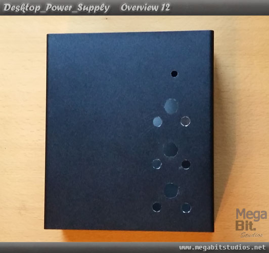
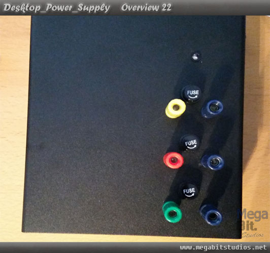
Once you have to template done copy it on to the case and mark out where you want your switch, LED's, banana sockets and fuses to go, i went with an led on the top , the 2 associated banana socket and the fuse to be in a small triangle cluster seen below and the other led and main power on switch to be on the back of the case with the PSU cut out.
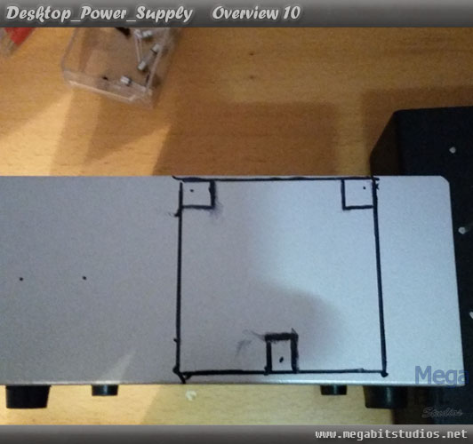
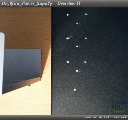
Once you have everything marked out centre punch all of your holes with a centre punch or any old screw driver you don't care about, after this start drilling the holes to suite the parts and cut out the hole for your PSU once you have finished it should look something like this.
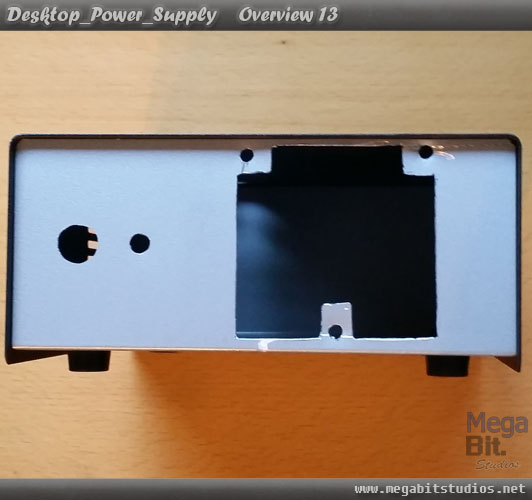
Now that everything is cut and drilled use a file & sandpaper to take off all the sharp edges and make it nice.
Attaching The Parts, Wiring & Soldering
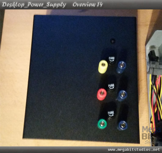
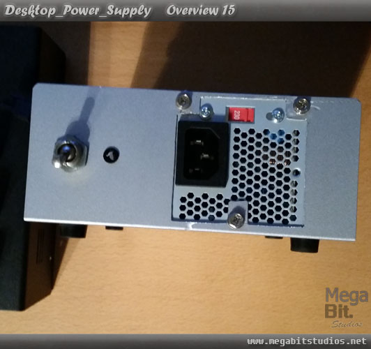
now that all of the hols are drilled and the cut out for the PSU is done its time to attach all of the parts once done you should now have something that look like this.
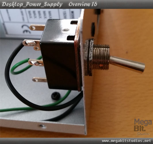
Ok so now for the wiring let's get the power switch out of the way first, cut the green wire off of the 24 ping connector and strip back the wire do the same with one of the black wires as well, it doesn't matter what one you select. now this is done solder the green wire to the middle prong on the power switch and the black one to the top prong, this will make it so when the toggle switch is in the up position it will tell the PSU to turn on.
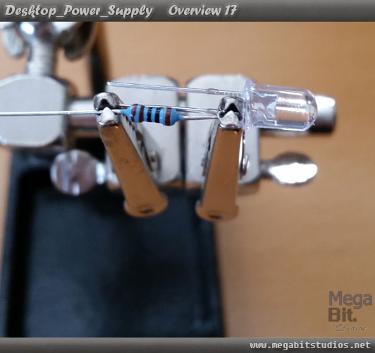
Grab one of the LEDs and solder one of the resistors to the positive lead (the longest one of the 2) once done it should look something like this
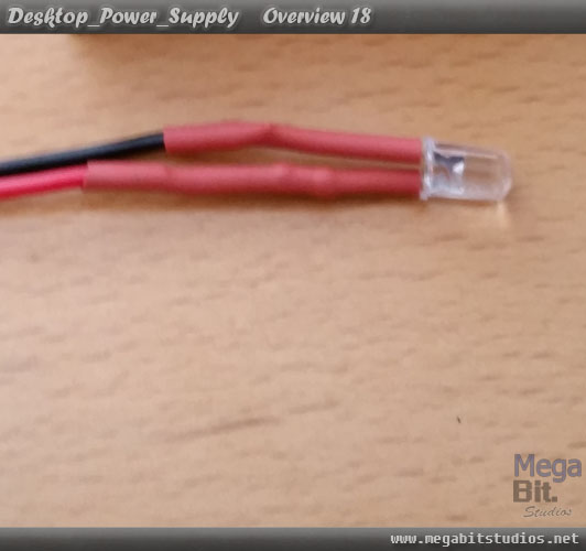
Trim the lead of the led off the back of the resistor so it nice and neat, cut a piece of Black wire from your spindle of wire big enough so that the other led can reach to where it need to be in the case slip a bit of heat shrink over the wire and strip the wire back and solder it to the negative lead of the LED (the shortest lead of the 2), then cut another piece of red wire from your spindle of wire big enough so that the other led can reach to where it need to be in the case, slip another bit of heat shrink over the red wire and solder it on to the back of the resistor, now pull the heat shrink over the 2 leads then shrink it with a lighter or a heat gun.
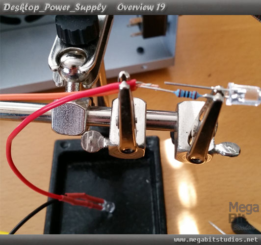
Now solder another resistor to the second one led like the first one , cut off one of the orange wires from the 24 pin PSU connector and twist it together with the red cable from the first led slip a bit of heat shrink over the 2 wires and solder it to the back of the resistors, do the same thing with a black wire from the 24 pin connector and the black wire from the first LED and solder it to the negative lead of the LED.
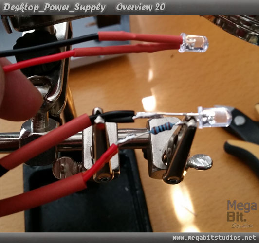
Heat shrink them, attach the led to the case and they are ready to go.
(note: at this point you can power the PSU on to test the LEDs)
Now we are going to connect up the banana sockets, cut 2 of the yellow wires from the 24pin connector and strip them back
(Note: if you have put a bigger fuse for a higher amp draw cut off more wires to suite your requirements)
twist them together and solder them to one side of the fuse holder that is going to be used for the 12V connection the yellow banana socket, repeat for the other 2 sockets cut 2 red wires from the 24 pin connector for the 5V for Red banana sockets, and 2 orange for the 3.3V green socket. next cut 3 wires from your spindle of wire that are long enough to reach from the fuse holder to the banana sockets strip them back on bother ends and attach each one to the other side of the fuse holder now you should have something that look like this.
Now for the crimping cut off 6 black wires from the 24 pin power connector and strip each one back twist 2 together to make 3 pairs on the end of each pair attach a Eye Crimp Terminal and attach the Eye Terminal to the black banana socket, now from the wires coming off the other side of the fuse holder crimp an Eye Terminal to each one and attach the terminal to their banana socket, the fuse holder with the yellow wires 12V attach to the yellow banana socket, the fuse holder with the red wire 5V to the red banana socket and finally the fuse holder with the orange wire to the green banana socket.
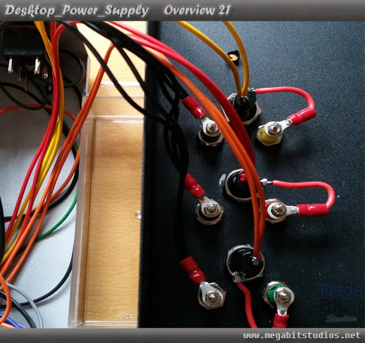
Now tidy up all of the cables attach the LED to their socket and put the case together and put the fuses in the fuse holders.
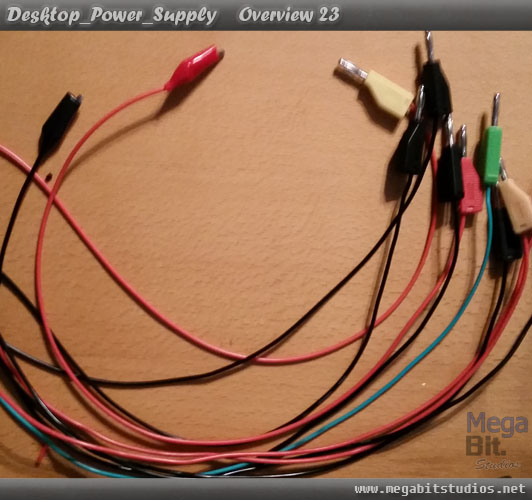
Making the test leads
This part is simple just cut 30cm fly leads from the spindle of wire, solder the leads you need to the end of them banana plug and alligator clip and so on until you have made the leads you require.
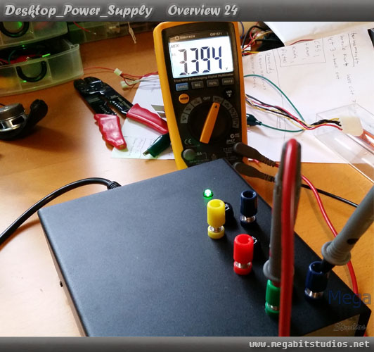
Finishing up and testing
Now we have everything put together clean up the case so its nice and neat then plug it in to the mains then power it up test the voltages Yellow should be around 12V +0.02 or -0.02 of a volt, red should be 5V and green 3.3V if all of the voltages are with in error of margin and your good to go you now have a desktop power supply to use for any of you 12V, 5V or 3.3V need.
If you like this tutorial feel free to Check out any of Our Other tutorials At.